
Astrophotography troubleshooting · UK
Elongated stars: build a diagnosis before changing the rig
Use a controlled sequence of short and long exposures to investigate tracking, differential flexure, tilt and corrector spacing.
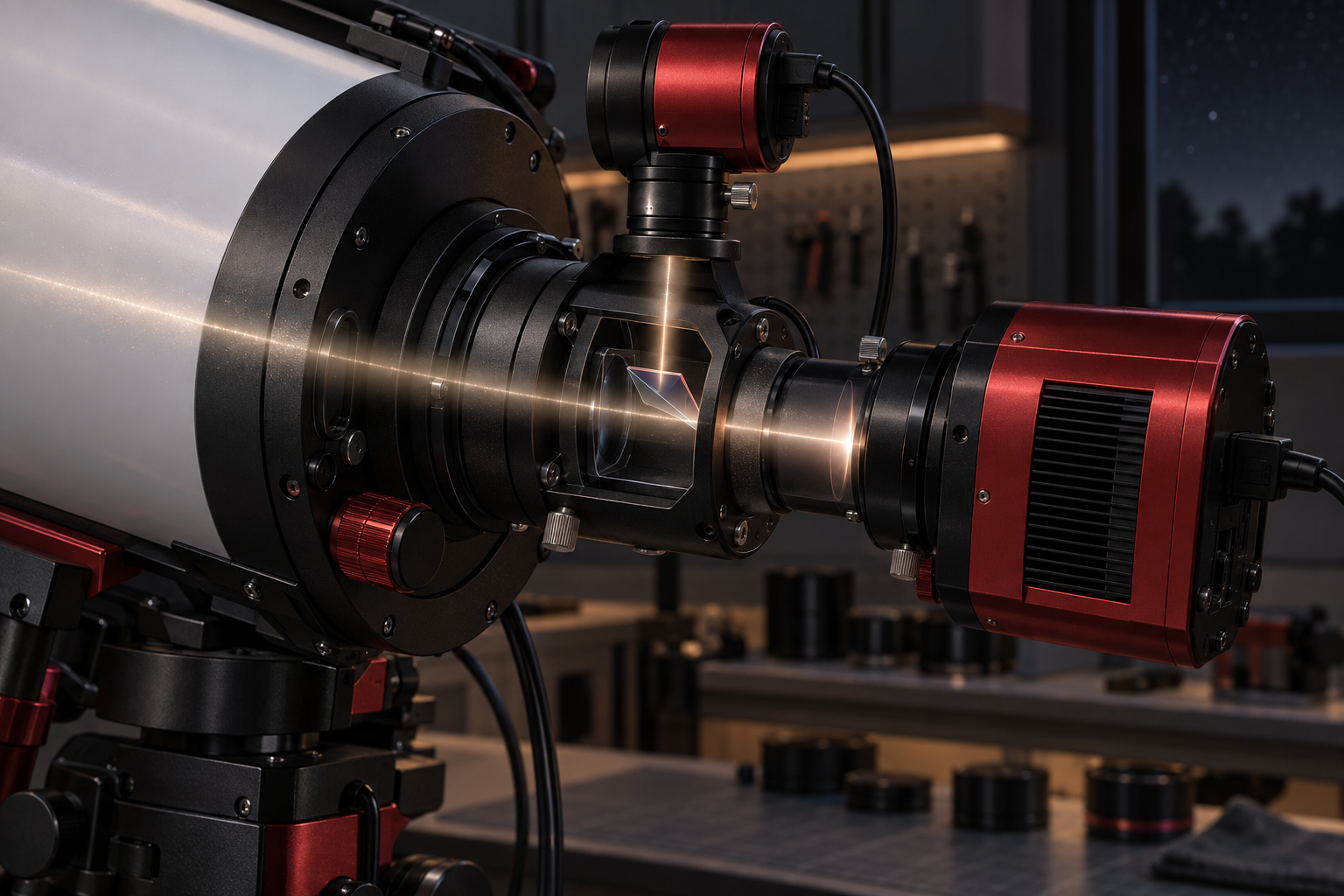
Start by comparing short and long exposures from the main camera, then investigate movement before changing optical spacing. Keep the original files, compare the centre and corners separately, and change one thing between test batches. Your aim is to identify the next justified adjustment rather than make every possible adjustment in one evening.
A tidy guiding graph cannot settle the question by itself. PHD2 explains that a separate guide scope cannot detect relative movement between its own optical assembly and the imaging telescope. Good guiding can therefore accompany elongated stars in the main camera. PHD2 differential-flexure guidance.
Make a baseline you can repeat
Choose a star-rich field and record the telescope, corrector, camera orientation, filter, adapter arrangement and focus procedure. Save a photograph or drawing of the optical train alongside the images. Give each test batch a name that describes the single change being tested.
For an initial comparison, take several short exposures and several at your intended imaging duration. These are diagnostic batches, so there is no prescribed exposure length here: use a short duration that still gives you enough clearly visible stars to compare. Keep the field, filter and camera orientation unchanged during the comparison.
Inspect individual frames before registration or stacking. Make matching crops of the centre and four corners, keeping the same display orientation and magnification. Write down whether the defect repeats, whether it becomes more obvious with exposure duration, and whether it affects the centre as well as the edges. These observations choose the next test; they do not establish a cause on their own.
First investigate movement
When longer exposures look worse, compare their timestamps with the guiding record and your notes about wind, cables and interruptions. Avoid immediately increasing guiding aggression. PHD2 distinguishes slow, predictable tracking errors from disturbances such as wind gusts, cable snags and vibration, which conventional guiding cannot reliably correct. PHD2 guide-algorithm explanation.
Check the existing guiding configuration before experimenting with individual controls. PHD2 recommends a Guiding Assistant run lasting several minutes when assessing declination behaviour. Follow its documented procedure and keep the result with your test images. PHD2 advanced settings.
Treat any improvement as provisional until it repeats in another batch. If you changed a guiding setting, keep the optical train untouched for that comparison. If you corrected an obvious cable obstruction, repeat the baseline before adjusting software as well. This gives you a usable record of which intervention helped.
Then test differential flexure
With a separate guide scope, persistent elongation despite apparently satisfactory guiding deserves a specific flexure check. PHD2 proposes finding a main-camera exposure duration with acceptably round stars, capturing a sequence with guiding active, then blinking the unregistered frames in capture order. Consistent movement between frames is evidence to investigate; an unregistered stack is another way to reveal the accumulated displacement. PHD2 differential-flexure test.
Keep deliberate dithers and other commanded movements outside this test sequence, and note any interruption. Otherwise, you have introduced an additional explanation for movement between frames.
The result does not identify a particular loose component. Record the guide-scope mounting, focuser connections and camera support as separate things to examine, following the equipment instructions. Our guide-scope or off-axis-guider guide helps frame the equipment decision if repeated evidence points towards relative movement.
Investigate persistent field differences
If short frames already show a repeatable difference across the field, preserve that evidence before touching tilt adjustments. ZWO identifies several possible contributors to field tilt, including the optical axis, flattener, adapters and sensor. An uneven field therefore does not establish that the camera sensor itself needs adjustment. ZWO field-tilt guidance.
Compare the same five crops across several frames. If a connection is suspect, use an appropriate supported adapter comparison and repeat the batch. ZWO includes changing a suspect adapter among its diagnostic steps. Record exactly which interface changed, since replacing an adapter may also alter the optical arrangement.
Leave model-specific screw adjustment until you have the exact instructions for your camera or tilt mechanism. This sequence deliberately stops short of prescribing screw directions or adjustment amounts: those details depend on the hardware.
Check spacing against the corrector specification
ZWO also identifies incorrect reducer-to-sensor spacing and an image circle smaller than the sensor as possible explanations for corner aberrations. A corner defect is therefore insufficient evidence for adding a spacer in a particular direction. ZWO corner-aberration guidance.
Before a spacing trial, retrieve the exact corrector instructions and identify the stated reference surface and required sensor distance. Use the backfocus spacing calculator alongside the spacing measurement guide to audit your recorded train. The manufacturer’s specification supplies the target.
If a supported spacing change is justified, record its amount, refocus and repeat the same image comparison. Keep tilt adjustment out of that batch. Compare the whole field, including any corner that became worse.
A hypothetical evening with a useful stopping point
Suppose several 15-second frames have acceptable stars, while 180-second frames show elongation. Those durations are hypothetical test choices, not recommended settings. You retain the optical arrangement and investigate movement first.
A further guided sequence at 15 seconds shows a consistent displacement when blinked without registration. That supports investigating differential flexure, but it does not prove which connection is responsible. You document one supported mechanical change and repeat the sequence before considering new equipment.
On another rig, the short frames might instead show the same poor corner repeatedly. That sends the investigation towards adapters, optical alignment and the corrector specification. The successful outcome is a defensible next step, with enough saved evidence to reverse an unsuccessful change.
Continue planning
Related guides
Power
Build an astrophotography power budget that survives the night
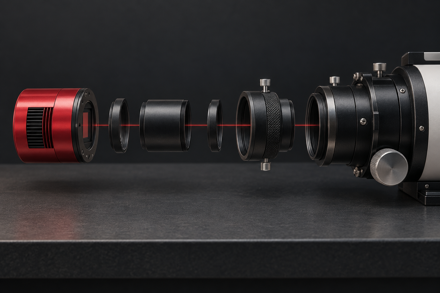
Optical train
Backfocus and spacing without guesswork

Smart telescope comparison